J. Kissel, L. Dartez
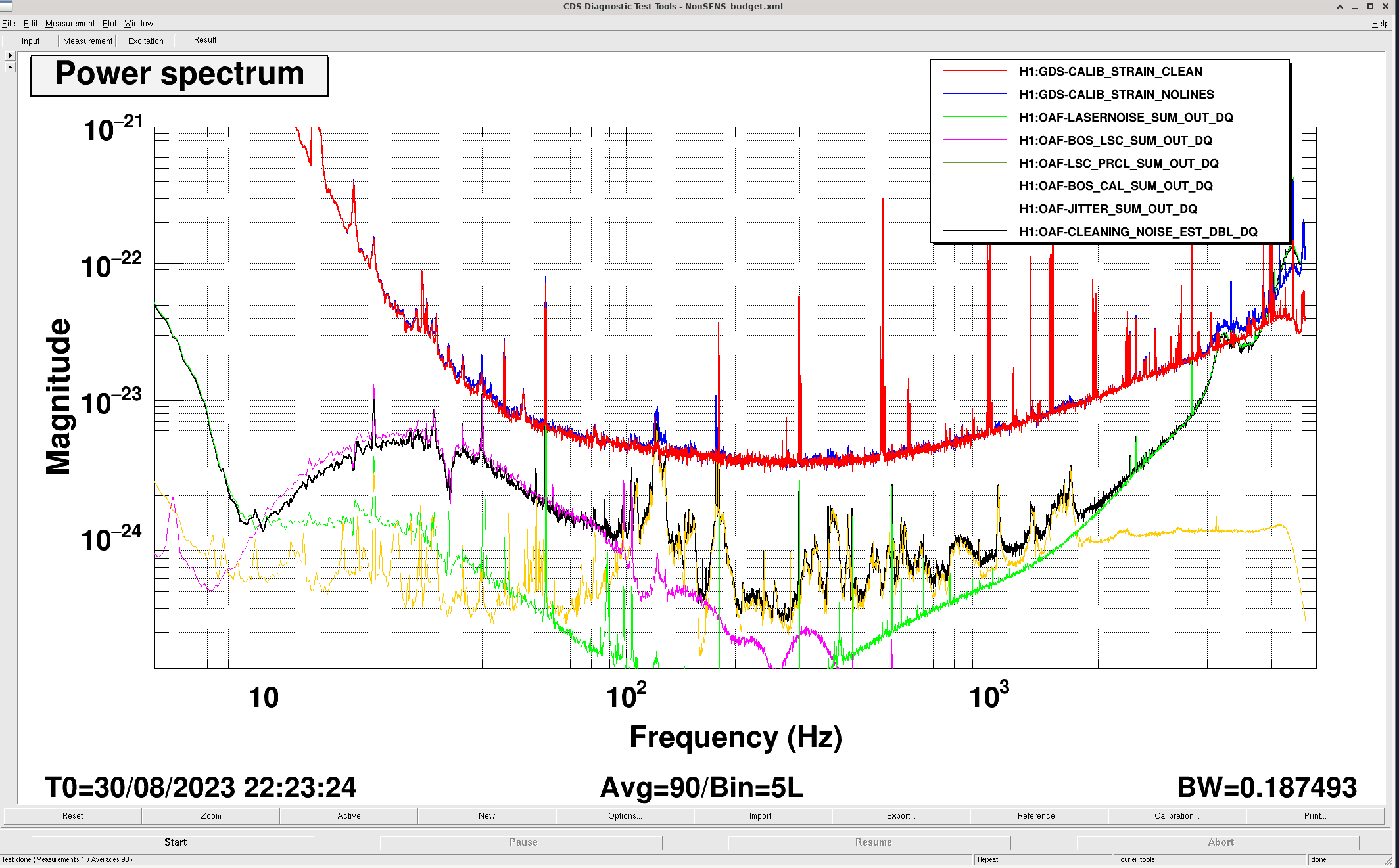
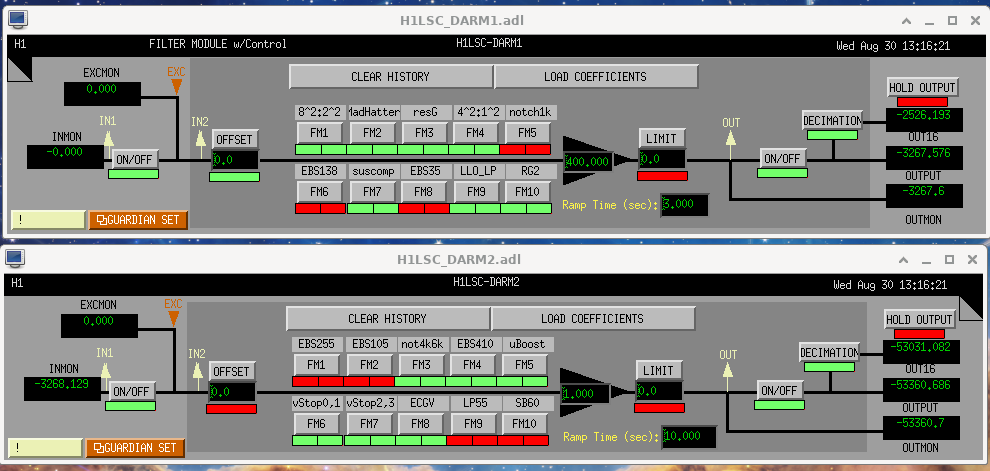
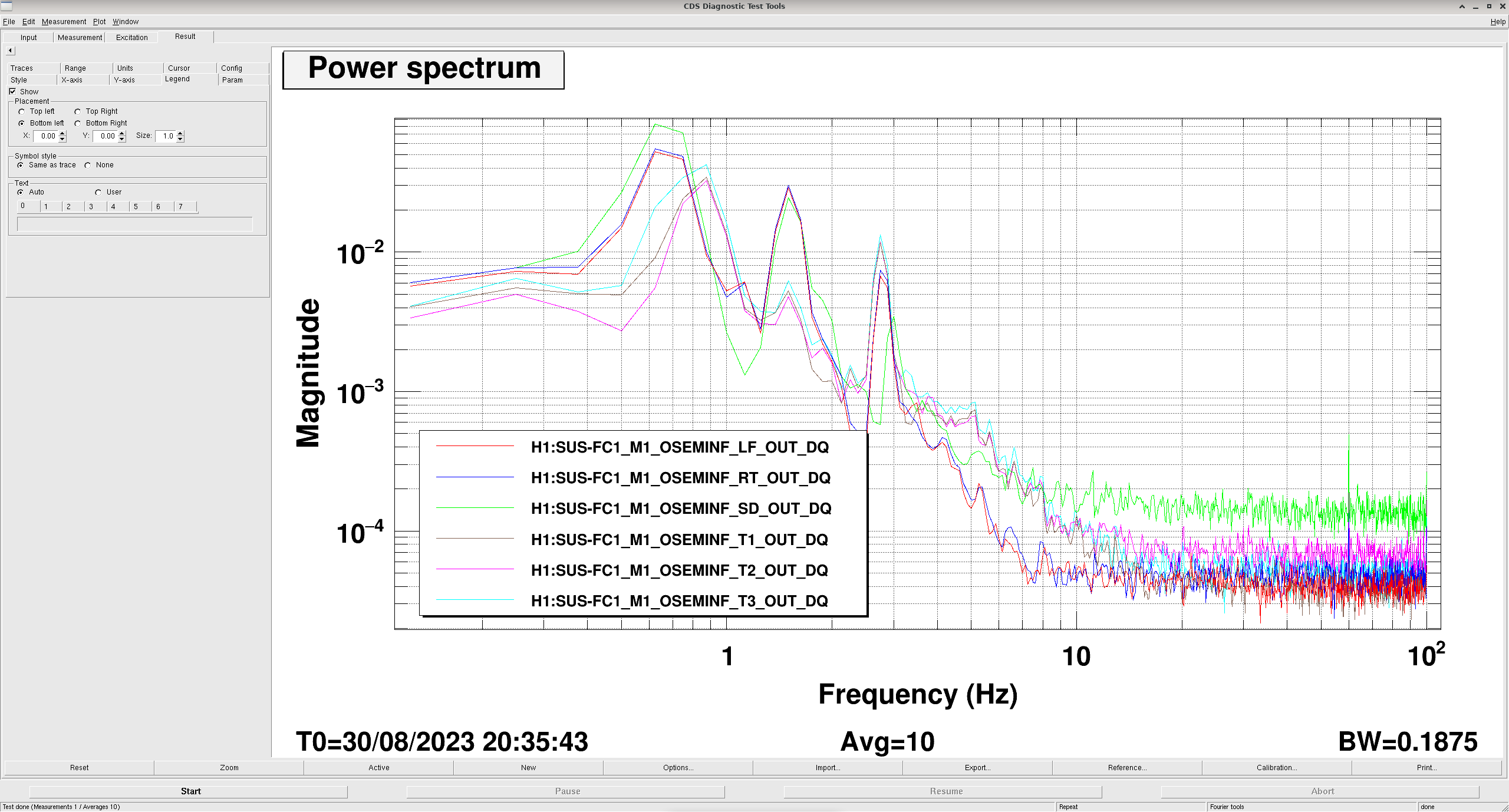
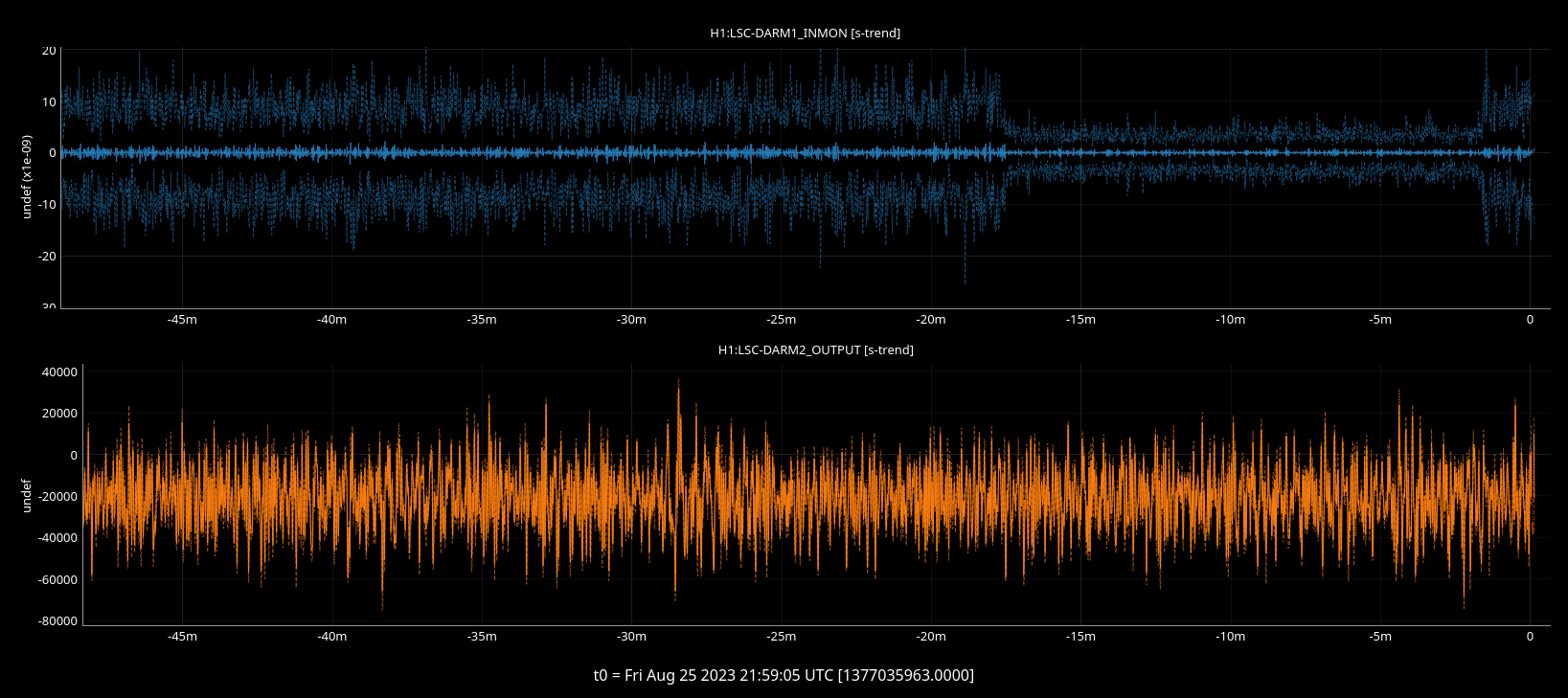
Given that we now like Gabriele / Elenna's new DARM2 boost filter in FM8, and it's been turned on permanently as of 2023-08-30 19:03:47 (12:03:47 PDT) -- see LHO:72562 -- we need to update the calibration infrastructure to handle it. Attached is a screenshot of the DARM1 and DARM2 filter banks as we want them now.
As such, we've done the following:
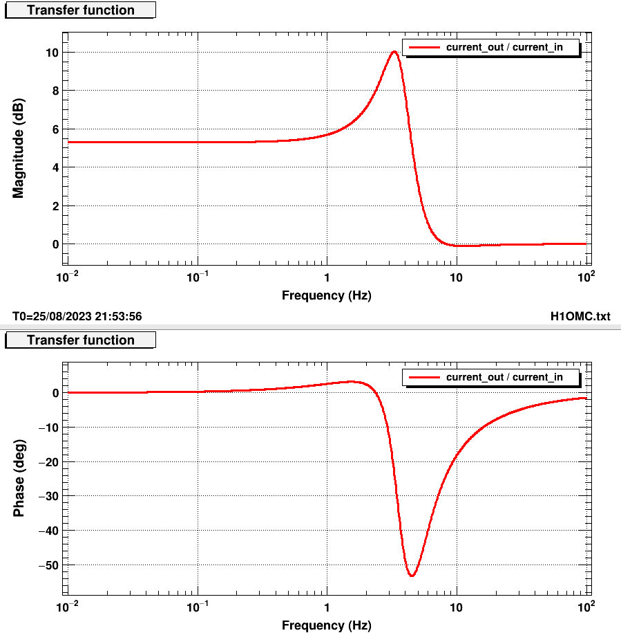
(1) Copy over the latest H1OMC.txt filter file (where we just have to know that that's where the DARM2 lives) that has the new filter in it over to the calibration SVN's filter archive.
$ chans
$ cd filter_archive/h1omc/
$ ls -ltr # to find the latest filter file -- is H1OMC_1377459704.txt, and it was modified at 2023-08-30 12:41 PDT
$ cp H1OMC_1377459704.txt /ligo/svncommon/CalSVN/aligocalibration/trunk/Common/H1CalFilterArchive/h1omc/
$ cd /ligo/svncommon/CalSVN/aligocalibration/trunk/Common/H1CalFilterArchive/h1omc/
$ svn add H1OMC_1377459704.txt
$ svn commit -m "(our commit message)"
(2) Update the call to this filter file, and the filter modules used in "the" pydarm parameter file.
(a) Make sure the local copy of the pydarm_H1.ini list of "static" parameters is up-to-date with no local changes.
$ cd /ligo/groups/cal/H1/ifo/
$ git fetch
# use a combination of
$ git status
$ gitk
$ git gui
# and just *looking* at the pydarm_H1.ini file to understand where things stand.
# We found that there were lots of local uncommitted changes from a major overhaul on July 30 where all comments were stripped from the file and variables were re-arranged
# We *think* there was no functional change, so we committed all the changes.
$ git add pydarm_H1.ini
$ git commit -m "(our commit message)" pydarm_H1.ini
# got some git crap about my email address not beign the right email address... had to
$ git config --global user.name "Jeff Kissel"
$ git config --global user.email jeffrey.kissel@ligo.org
$ git commit --amend --reset-author
# that popped open another message with vim interface, had to blindly hit enter or :wq, or q a bunch of times...
# ran
$ git log
# to confirm that we've staged the commit appropriately (and Louis assures me I have)
$ git push
This brings pydarm_H1.ini to git hash 0185c1d7.
(b) *Now* make the changes that we actually need to change,
$ gedit /ligo/groups/cal/H1/ifo/pydarm_H1.ini
# change line 48
digital_filter_modules = 1,2,3,4,7,9,10: 3,4,5,6,7 ==>> digital_filter_modules = 1,2,3,4,7,9,10: 3,4,5,6,7,8
# change line 50
digital_filter_file = cal_data/H1OMC_1336944438.txt ==>> digital_filter_file = cal_data/H1OMC_1377459704.txt
$ git add pydarm_H1.ini
$ git commit -m "(our commit message)" pydarm_H1.ini
$ git push
This brings pydarm_H1.ini to git hash 3c57e5f9.
(3) We *also* need to make sure that this "cal_data" folder is meaningful. So we have to update a disctionary inside the pydarm_cmd_H1.yaml "pydarm command line infrastructure parameter set,"
(a) We also checked the local status of this file against the mothership, and we see that there are also lots of uncommitted differences.
Louis assures me that he understands these differences, but we can't commit them now. *sigh*
(b) So, we changed the local file as it was.
# change line 78
digital_filter_file: "Common/H1CalFilterArchive/h1omc/H1OMC_1336944438.txt" ==>> digital_filter_file: "Common/H1CalFilterArchive/h1omc/H1OMC_1377459704.txt"
Again, this version of the pydarm_cmd_H1.yaml NOT yet committed.